The blog of a dedicated radio amateur and electronics enthusiast

"Having fun on the air and in the workshop - communicating and creating"

31 May 2016

Vacuum pen for pick 'n place

vacuum pen apparatus
pen and an assortment of nozzles
As I get older my hand is becoming too unsteady for using tweezers to pick and place certain types of surface mount components onto a pcb ready for reflow-soldering. I wanted to see if a vacuum pen would help.
I converted a really cheap aquarium compressor pump to work as a vacuum pump, by reversing the valve action. The 'pen' is a 5ml syringe; plunger not required. The 4mm bore tube for the air-line was passed through two rubber grommets and forced into the syringe. Hot-melt glue was applied inside the barrel of the syringe at the entry point of the tube to form another seal and reduce pipe movement. A small hole drilled into the syringe near the nozzle end makes a simple finger operated vacuum switch.
T-piece vacuum switch
For even better precision and control I subsequently fitted a T-piece for the vacuum switch, close to the pump, to be operated by my other hand. And I made another pen; of course with no hole. 

04 May 2016

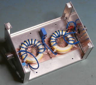
Half-wave filter for the MF amplifier

Two T200-26 iron powder toroids are used
It's called a half-wave filter because it functions like a half-wavelength of transmission line, ( e.g., coax cable ), regarding the terminating impedances at the design frequency of 475.5KHz. Using lumped circuit elements is a much more practical proposition than 200m of cable. It also has a low-pass frequency response; theoretically 2nd harmonic 951KHz -27dB, and 3rd harmonic 1426.5KHz -47.8dB. This is a useful amount of extra attenuation. So I built it for use with my MF amplifier, ( posted 6 December 2015 ), to provide additional suppression of harmonics in the transmitted signal. It is connected externally in-line with the amplifier output.  

09 January 2016

Schmidt trigger input for the dual band amplifier

50% +DUT drive signal on the gate of one of the four MOSFETs
Schmidt trigger circuit installed
I have improved the amplifier efficiency by increasing the duty cycle ( +DUT ) of the drive signal on the MOSFETs' gates from 43% to 50% with the addition of a Schmidt trigger first stage. After experimenting with several CMOS NAND and inverter logic chips, ( i.e., CD4093BE, CD74HCT132E, SN74HC14N, SN74HCT14N ), which already have Schmidt trigger inputs, I found I could only obtain the 50% +DUT I wanted by making my own Schmidt trigger circuit using a quad 2-input NOR gate chip ( CD4001BCN or HEF4001BP ). I eventually decided to retain the older CD4001BCN in the circuit as the low pulse rate doesn't really justify using the newer HEF4001BP for this application. I built the circuit on a tiny piece of pad board and fitted it above the main driver circuit board. ( See also post dated 6 December 2015 ).