The blog of a dedicated radio amateur and electronics enthusiast

"Having fun on the air and in the workshop - communicating and creating"

30 September 2020

UV Radiation Meter

Frequent or prolonged exposure to high levels of solar ultra-violet (UV) radiation can damage the skin. But how can we know exactly what that level is ?
I've designed a UV Radiation Meter to measure and display ultra-violet light radiation from the sun. It will be useful to quantify what UV radiation level I am actually exposed to when outside, particularly in summer, though I do normally take the precaution of at least wearing reactive spectacles and a hat.
The meter is based on the Silicon Labs SI1145 UV Index sensor, ( with I2C interface - see 27 March 2019 ), and the Heltec WiFi Kit 32 (HTIT-WB32) ESP32 development board with blue OLED display which I featured in the last post. It has an internal 3.7V 1000mAh Lithium battery which gives about 17.5 hours of continuous operation, and can be recharged in-situ by USB; charging time 3 hours 40 mins. I chose a stylish white hand-held enclosure; it looks quite smart.
UV Index, ( zero to 11+ ), and UV Level are displayed according to the W.H.O. definitions; Low, Moderate, High, Very High & Extreme.
UV meter displaying an indoor measurement
In the image above, access to the micro usb connector for battery charging and programming is on the left.
I completed it too late for using it much this year; but it's ready and waiting for next summer.
( W.H.O = World Health Organisation )

02 August 2020

Wi-Fi and Bluetooth with ESP8266 & ESP32

Several years ago I began experimenting with Wi-Fi using modules based upon the ESP8266 family of devices manufactured by Espressif Systems in Shanghai. They are microcontroller chips with built-in 2.4GHz Wi-Fi capability. Development boards using these chips are readily available at very low cost from many different suppliers. At first I used the basic ESP8266-01 incorporating the ESP8266EX chip, and then progressed to boards with more functionality ( I/O, serial comms, ADC etc ) i.e., the NodeMCU-12E using the ESP8266MOD. I was thinking about some IoT ( Internet of Things ) applications. Although I made some gadgets, nothing was actually being controlled remotely. Eventually I moved on to other activities.
However, my interest in this topic returned recently after discovering the successor to the ESP8266, namely the ESP32, ( 32bit, 240MHz clock & more memory ), with both built-in Wi-Fi and Bluetooth ( classic Bluetooth & Bluetooth Low Energy, BLE, server & client ) capability; also development boards incorporating the ESP32 such as the NodeMCU-32S and some others including a video camera ( ESP32-CAM ) or an OLED display ( Heltec WiFi Kit 32 ). All these remarkable devices cost only a few dollars.
My collection of Wi-Fi & Bluetooth development modules
In the above image, left to right :-
NodeMCU-12E, Wi-Fi only.
NodeMCU-32S, Wi-Fi and Bluetooth.
WiFi Kit 32, Wi-Fi and Bluetooth, 128 x 64 px OLED display.
ESP32-CAM, Wi-Fi and Bluetooth, 2Mpx video camera, 4GB uSD card slot.
ESP8266-01, Wi-Fi only.

Perhaps I'll make a BLE server to notify a value from an unusual sensor; e.g., air quality, charged particles, UV, magnetic field. ( Obviously for my personal experimental use in my private capacity as a hobbyist. )

( I tweeted updates to this post on 5 August 2020 and 12 August 2020. Click on the link on the left ).

05 July 2020

SpaceLabs MicroTrackers

On 6 October and 24 November 2019 I briefly described a future project using a GNSS receiver module with a microcontroller and a display, to parse GPS NMEA text strings and display my choice of data in an easy-to-read form.
I have now completed 3 versions using different firmware, GNSS receivers, microcontroller development boards, and displays. I call them "SpaceLabs MicroTrackers".
Depending on the version, date, time, latitude, longitude, altitude, nr. satellites acquired, fix quality, and update age are displayed. Features they all have in common are a 25x25mm active ceramic patch antenna, USB interface for programming/power and Ublox Neo-6M compatible GNSS receiver module.
While waiting for enough satellites to be acquired for a position fix, version details, local temperature and battery voltage are displayed. I also designed some graphics using bitmap byte arrays and scrolling animation.

MicroTracker-3 with Arduino board, 128x64px Oled display
MicroTracker-2 with PIC board, 128x32px Oled display
MicroTracker-4 with Arduino board, 84x48px Nokia 5110 display

On MicroTracker-4 I have provided a 1 pulse per second ( 1pps ) signal on an external connector. This is an extremely accurate 1Hz pulse ( 10% duty cycle ) locked to the satellites' atomic clock. When locked-on, a LED on the GNSS receiver module flashes on/off once a second.
Waveform of 1pps signal from MicroTracker-4

A second usb socket on MicroTracker-4 gives access to the GNSS receiver module for changing its settings and displaying complete NMEA sentences on a serial terminal.
 
My recent experience gained with OLED and Nokia 5110 displays has been put to practical use.

10 June 2020

Nokia 5110 Liquid Crystal Display

I recently discovered surplus Nokia 5110 Liquid Crystal Displays ( LCD ) which were used in Nokia 5110 phones, circa 1998. Thousands of these interesting display modules are available at on-line auction sites. I bought four, about GBP2.30 each; two having a blue back-light and two with white. The resolution is 84 x 48 pixels; overall dimensions 4.5 x 4.5cms. The controller/driver chip is PCD8544. I searched for and downloaded the data sheet; essential reading !
Nokia 5110 LCD types: back-light colour (L) blue (R) white
Communicating with the display uses the SPI ( Serial Peripheral Interface ) bus specification, which is a synchronous MASTER/SLAVE configuration with the MASTER generating the clock. As well as supply and ground, the following 5 connections to the display are needed; Chip Enable ( CE ), Serial Clock ( CLK ), & Serial Data ( DIN ), and additionally, for control purposes, Data/Command ( DC ), and Reset ( RST ). Back-light ( BL ) connection is optional.
6 config bytes being sent to display on SPI: top CE, mid CLK, bottom DIN
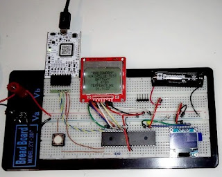
Basically, using the display requires (i) configuring display settings, and (ii) knowing how the addressing of the DDRAM works when writing data for displaying. To try out the display I connected it to the PIC microcontroller ( MSSP module ) on my prototyping board, and ran some code to measure and display temperature and voltage. The bus speed I chose was 1MBit/s.
The display lacks a built-in font. But that was quickly remedied by finding a ASCII character set 5x7pixel font file online, and including it as a header file in my C-code.
Nokia 5110 LCD with white back-light in use
I was disappointed with the blue back-lit display being hard to read, despite spending a lot of time experimenting with contrast, bias and temperature coefficient settings. The white back-light variant is much better in this respect.
I found the display very easy to use; now ready for a suitable future project.
( Click on images to zoom ).
MSSP = Master Synchronous Serial Port, DDRAM = Display Data RAM

20 January 2020

Upgrading my design tools for PIC projects

2020 has just begun, and here is my new year's  resolution, which I have already completed !
For my embedded control projects it was time to standardise on PIC microcontrollers, ( e.g., the PIC16F188** family ), belonging to a newer generation than some of those I had previously been using. PIC development in recent years has now led to devices typically having larger memory, supporting higher clock speeds, with more peripherals including core independent peripherals, and new features, such as peripheral pin select, device information area, configurable logic cell, integrated temperature sensors to name a few.

The new development platform for my embedded control projects
As result I have had to upgrade my hardware tools as well for compatibility; the most significant change being the MicroChip "Snap" programmer/debugger, to replace my obsolete ICD2, and a different prototyping board, which I could call MyDev3, ( see post dated 2 November 2010 ). The MCU featured in the image is a 40 pin 8-bit device, MicroChip PIC part PIC16F18875/P. ( Click on image to zoom ).
All is working fine. The PIC was a new unused blank device and successfully programed with my TEMPSENS-OLED firmware. ( See post dated 6 October 2019 ).
MCU = MicroController Unit, PIC = Programmable Integrated Circuit from MicroChip Inc.