The blog of a dedicated radio amateur and electronics enthusiast

"Having fun on the air and in the workshop - communicating and creating"

22 September 2014

A compact transmitter power amplifier for 475KHz

Internal view: Right - input circuit, Left - output circuit and fan
Ex-pc power supply cases are ideal for small projects
With the previous amplifier, ( see 14 February ), I contacted a couple of countries on the 475KHz/630m band. I have now replaced that amplifier with a more efficient Class 'E' design. It uses a type IRF640N mosfet and 13.8Vdc supply to produce an output power of 50 watts with an efficiency of about 81%.
I built the amplifier in an old pc power supply case, measuring just 165 x 90 x 85mm, retaining only the original fan.
During the evenings I have been transmitting a beacon signal on 478.5KHz using my DDS frequency synthesiser as the drive signal source, and been getting reception reports from across Europe. So far Essex in England at 1380Kms is the farthest that reception of my signal has been confirmed. If the amplifier remains healthy during these tests I shall attempt to increase the output power to about 140 watts, and start making some more two-way contacts with other radio amateurs on the band.

19.10.2014. Till now my 50 watt beacon transmission has been received the farthest in NW England at 1602kms, and my 'countries-worked' total has risen to 4; Poland, Germany, Finland and France. So as planned, I have increased the output power of the amplifier to 140 watts by connecting it to a 24Vdc supply. The efficiency has improved to 86%.
01 July 2014

ARM - Advanced Reduced instruction set Microcontroller

Having used 8bit devices, ( PIC16f/18f, Atmega328 ), for several years, I shall be taking my future projects with embedded control to the next level with ARM Cortex-M3 core architecture 32bit processors. I have bought two ARM development boards, each having the 20 pin JTAG interface but a different processor from the STM32 family. Being so cheap these boards are ideal for the electronics hobbyist wanting to develop some really amazing hi-tech applications. I have downloaded two IDE's, ( Integrated Development Environment ), to try; emIDE and Keil uVision4. I also have the Segger J-Link, JTAG compatible, programmer and debugger, ( not shown in the pic below ).
That completes my preparations. Now I just have to think of a project to work on during the long winter evenings to come.
l
STM32F207VCT6 (l) and STM32F103RBT6 (r) ARM development boards

18 March 2014

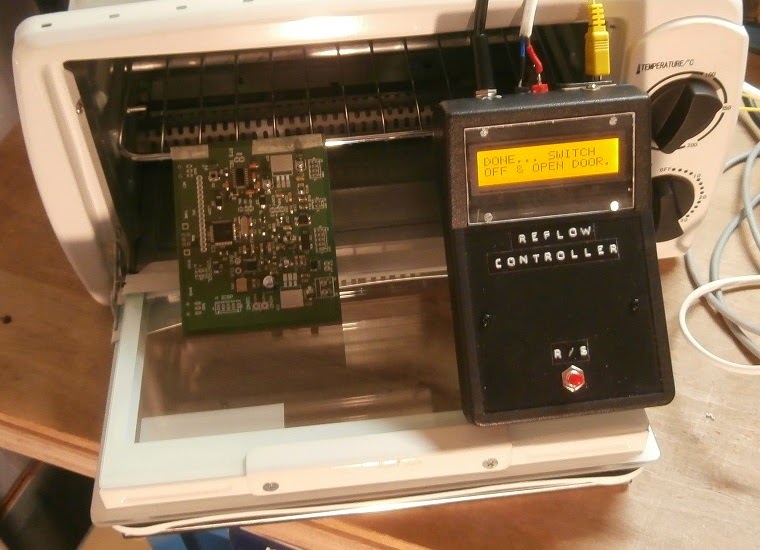
Reflow soldering - Part (6) First circuit board soldered

"Done... Switch off and open door"
The first circuit board has had the surface-mount components soldered onto it using my new reflow-soldering system. On close inspection afterwards, there was no sign of any heat damage and no repairs or rework were necessary. The tiny parts all seemed to be perfectly soldered.  I later soldered the through-hole-terminated connectors and switches with a soldering iron.
As soon as the board was back to room temperature, I powered it up and successfully programmed the PIC microcontroller. Some initial electrical tests were also positive.
Earlier I had spent some time practicing picking up, holding steadily and placing the parts in a controlled manner onto the circuit board. After the solder paste has been applied there is limited time. A mistake would probably smear the paste, requiring cleaning and start-over. I found tweezers, curved at the ends, to be the best. In the interests of speed, I first took all the components I would be needing from my stock, and separated them by type in a compartmented tray. I decided to place the 44 pin PIC on the board first as a mistake was most likely to occur with the placement of that component.    

08 March 2014

Reflow soldering - Part (5) Using the stencil

Preparing to apply the solder paste
I now have the stencils through which solder paste is applied to the printed circuit board ( PCB ). The material is 0.1mm thick stainless steel. Manufactured using a laser cutting process, the minimum cut-out dimension and spacing is also 0.1mm. However the steel was far more suitable for laser cutting than the transparencies, mylar and plastic materials which were also evaluated.
The PCB is held securely between spare PCBs, or off-cuts of other material having exactly the same thickness as the circuit board; checked with vernier calipers. The stencil is then aligned on top so that the solder pads, ( where the SMT parts will be placed ), are visible, and then one edge is taped down to form a hinge.
I use two spreaders; a small spatula and a plastic card. The spatula is for getting the solder paste out of the pot and, after transferring the paste, the card is used to spread the paste over the stencil. As the paste is not cheap, any excess is returned to the pot.


14 February 2014

Getting ready for 630 metres

Experimental amplifier for 475KHz using a single 32N12 mosfet
Just a few days ago I read that the 630m / 475KHz band will be released to radio amateurs in Poland from 18 February. Having no transmitter for that band and wanting to radiate a signal from the first moment the band becomes available, I had to make something very quickly. It was a race against time and all I could hope to complete was an amplifier, ( based on a type 32N12PV2 mosfet device ), to boost the output signal of my frequency synthesizer by about 26dB.
For the antenna, I plan to use my existing 46m end-fed wire, ( posted on 12 August 2011 ), and part of the loading coil I already use on the 2190m / 136KHz band; ( posted on 19 February 2010 ).
With this setup I shall be amazed if I can even make contact with local radio amateurs, ( let's say those up to 10Kms away ), assuming there will be any of them also equipped and active on the band at the start. Still, it's worth a try.

26 January 2014

Logic analyser

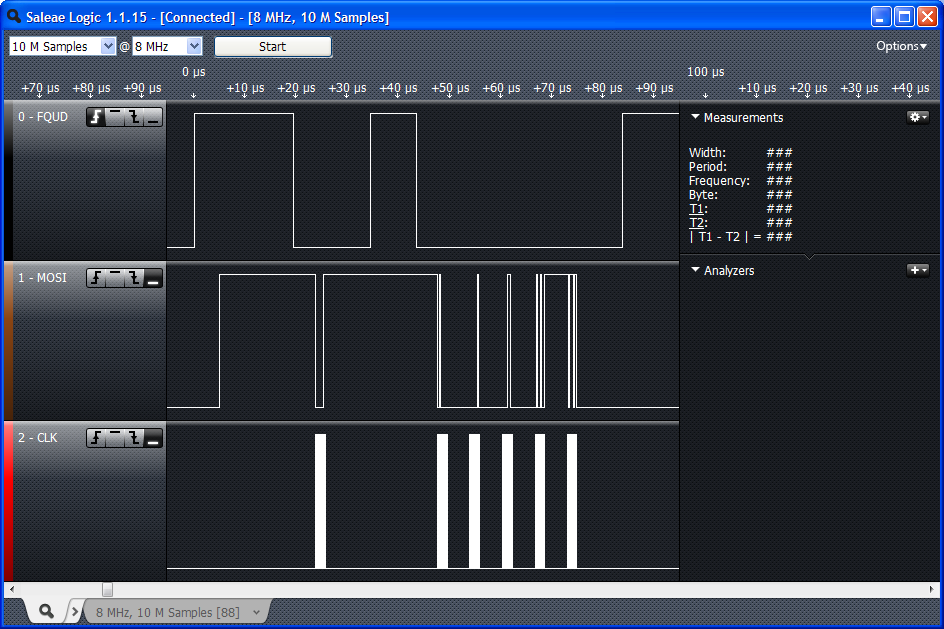
Top-bottom: frequency update, data, clock
First data byte magnified - 8 clock pulses send 00000011
Arduino 'Uno' board and logic analyser connected
I have a new toy to play with; the Saleae 24MHz 8 channel logic analyser. Looking for some signals to analyse with it, I programmed my Arduino board's SPI ( serial peripheral interface ) pins, incorporating the appropriate library code, to send frequency update pulses, 4MHz clock and 6 bytes of data to an AD9850 DDS chip. I was unsure how the SPI modes had been implemented in the library code. With the logic analyser connected I was quickly able to determine where my own code required modification so that the desired signals were obtained.
I needed 3 of the 8 available channels of the logic analyser. Previously I would have had to use my dual channel oscilloscope, viewing only 2 signals at once.