The blog of a dedicated radio amateur and electronics enthusiast

"Having fun on the air and in the workshop - communicating and creating"

14 September 2011

MyDev2 enhanced

Schematic - note Vcc connection depends on usb-powered or self-powered application
I have upgraded to version 3 my PIC MCU development platform, MyDev2, ( first posted on November 2nd, 2010 ), with the addition of pull-down resistors R25-R28 for the keypad rows connections now that I have decided on the method I will use in coding the operation of the keypad and the interfacing required to the microcontroller. I have already started writing the code in 'C' programming language, instead of the 'Assembly' language which I have used for all my PIC projects until now. The keypad will be a 'telephone' style 4 row x 3 column, 0-9, # and * type.
I have also fitted a new microcontroller type, Microchip part PIC18LF4455-I/P, which, as well as being a few cents cheaper than the original PIC18F4550 and PIC18F4685, has an extended operating voltage range, ( denoted by the 'L' in the part number ), down to +2V, as I want to experiment with coding the detection of switching off the power !

23 August 2011

New antenna radiates

The new antenna for longwave, mentioned last time, radiates. I have been making some test transmissions on 137.7KHz and these transmissions have been received by Jacek, callsign SQ5BPF, on the other side of Warsaw. The screen capture below shows how he saw my signal on his 'lf grabber'. Incidentally, he could also hear it.
So now I have a reference signal with which to compare future signals as I make improvements to the antenna installation; the aim being to make the signal stronger and the signal trace white rather than the orange colour it is now. Losses in the system have to be reduced. To achieve this, I shall start by burying more copper in the garden. This will be a very labour intensive and time consuming activity. I shall probably be eaten alive by mosquitos before completion ! I hope to report total success in the near future - if I survive the ordeal.

12 August 2011

Wire in the sky


I have erected a new antenna in readiness for the restart of my radio activity on the 136KHz 2190m longwave band during the coming autumn and winter season; simply a 45.9m long wire, and a number of bare copper conductors buried in the ground directly below. The wire is supported at the mid point by a fibreglass pole, and a spring counter-weight ( see inset ) running through a pulley tied at the highest point I could reach to a tree at the far end.
The (in)famous loading coil, ( posts dated Feb 19th & Sept 13th 2010 ), will still have to be pressed into service; but fortunately it will be installed inside my radio room. What a huge relief that I will no longer have to use the coil outdoors or carry out frequent maintenance on it inspite of the snow and ice, as with the previous antenna !
My last attempt to put up a different antenna for long wave was in 2009. It was a much more complex design, both electrically and mechanically, requiring 'miles' of wire. It would have been an excellent performer. Sadly it never came to fruition, being blown down / away four times during summer thunder storms before I had even finished building it. There was an important lesson to be learnt from that ! It's better to have a simple antenna than no antenna.
While the performance of the new antenna will be inferior to the one I didn't complete, it should out-perform the last operational one.

12 July 2011

Then there were four

From time to time since the last post, ( 16 June ), I have been populating three more circuit boards; four are now complete. This is not quite the rate of 3 per week which should be achievable, single-handed; what an efficient production line that would be !
During this activity my soldering skills working with surface mount components, some minute, have quickly improved. Surprisingly, I didn't find the 44 pin microcontroller chip to be the most difficult to mount.
Now I will progress further with the case. I have already finished the technical drawings for the top, base, front and rear panels ready for their fabrication. And today a local firm precisely cut the extruded, anodised aluminium sides to the final length.

16 June 2011

Densely populated

A new batch of Analog Devices synthesiser chips has arrived, enabling me to finish populating one circuit board with components. I programmed the PIC MCU via the bootloader with my latest v2.00 code and, after powering up the board, all seems to be working fine.

11 April 2011

BF991 receiver RF preamplifier completed

While waiting for the boardhouse to make the printed circuit boards for my frequency synthesiser, ( see post on Mar 8, 2011 ), I reckoned I should have just enough time at long last to build the low noise 144MHz receiver RF preamplifier which I designed months ago, ( see post on June 16, 2010 for circuit schematic ).  For this piece of equipment I again made the pcb; the artwork for it is shown, ( actual size 4.2" x 2.2" ).
I built the circuit on single-sided copper laminated fibre-glass board, all components being mounted on the same side as the tracks and copper ground-plane; in effect surface mount technology even though only the BF991 mosfet, in a SOT143 package, is actually a surface mount device. A piece of double-sided board material was soldered vertically across the circuit board to act as a screen to prevent coupling between the input and output tuned circuits. The preamplifier is housed in a Hammond "Eddystone line" type 27134PSLA die-cast metal enclosure, 111x60x31mm.
Being somewhat larger than a matchbox, it's not the tinyest rf preamplifier that I have ever seen. Small size is not an issue for me, as it will not be installed internally in any other equipment but used outdoors close to the antenna. Besides that, the heavy-duty change-over relays that will be necessary to divert the transmitted signal around the preamplifier will add significantly to the overall size anyway.
Achieving a low noise figure for the preamplifier is strongly dependent on the C-C-L input bandpass filter and matching circuit which should use low loss, ( i.e., high 'Q' ), components. I easily obtained some suitable ceramic trimmer capacitors for C1 and C2, but sadly no silver plated wire from which to make the coil L1 !

08 March 2011

The art of pcb design

 
Coincidentally, the rotary encoders and Microchip microcontrollers for the current version of the frequency synthesiser project both came in the post today; one of each is required in each synthesiser. I had been waiting especially for the arrival of the encoders as I had to create that part in a new component library inside the CAD software so that I could complete the artwork for the track layout of the double-sided printed circuit board.
Microchip had protected the microcontrollers in a little plastic box, ( like a presentation box for jewellery, rings etc), lined with static dissipative foam. I must say that this level of care impressed me ! A pity, though, that both chips flew out when I opened the box for the first time.
An encoder and microcontroller will be in the positions of SW1 and IC1 respectively. For clarity, just for this posting, the picture of the pcb design, ( actual size 4.0" x 3.2" ), doesn't show the copper-fill for the ground-plane on the topside. I have made pcb's many times in the past for various projects; but this one will have to be manufactured commercially.
The encoder is an Alps part, type EC11B152420Q, ( having 30 positions and 15 pulses per revolution plus switch ), and the Microchip microcontroller is type 18F4550-I/PT, in a 44 pin thin quad flatpack (TQFP) plastic package.

22 February 2011

Winter's icy grip

Cold air from Scandinavia brings freezing weather conditions to Poland with temperatures well below 0C. I recorded -16.5C overnight last night and -21C is forecast for tonight. Although today was clear and sunny the temperature was still only -10C to -12C. Sun illumination level was high today, making it possible to receive some nice images transmitted by the NOAA weather satellites. I received the one shown above from NOAA18 at 1131gmt on 137.9125MHz.

10 February 2011

Bootloader in action


After programming a boot-vector and boot-block into the PIC microcontroller's flash program memory, I used a bootloader to upload my application code to the PIC from the PC using its com port, the level converter, ( featured yesterday ), and the EUSART, ( enhanced universal synchronous asynchronous receiver transmitter ), connections on the PIC. The top picture shows all the project hardware, looking a bit untidy by now.
To check, I read back from the PIC to the bootloader the entire contents of program memory, ( actually also data eeprom and config ). The screen capture in the lower picture shows just the first portion of this, from address 0000hex to address 00DFhex. On looking at this I can see that the bootloader has highlighted the boot-vector code, at address 0000hex - 0003hex; the high priority interrupt vector and low priority interrupt vector are still at 0008hex - 000Bhex, and 0018hex - 001Bhex respectively. My PIC type, com port and speed are correctly declared in the bottom right corner. I notice that the time taken for the flash memory 'read' was 35 seconds. I'll configure com2 for a higher speed to reduce this, although I won't be reading memory very often. I recall that, earlier, 'writing' took only 4 seconds.(*)
It'll be interesting to use the bootloader for programming instead of the ICD2, which of course will still be essential for debugging.
All this has got me thinking about the download area on my eventual (?) website !
( My thanks to Microchip Technology Inc. for the freeware serial bootloader AN1310v1.04 )

* Update, 11 February : I subsequently changed the speed of com2 from 9600 to 115200 bits per second; now write and read times have been reduced to 0.942 and 2.975 seconds respectively.

08 February 2011

PC talks to PIC projects


Today I built a CMOS/TTL to RS-232 level converter using a Texas Instruments part, MAX232N, driver/receiver chip in a 16pin DIP package. Now, provided that the PIC is self-programmable, ( which indeed my PIC18F4550 is ), it will be possible to connect my PIC applications/firmware to a PC serial ( com ) port, or via a USB (*) adaptor.The purpose of this interface between PC and PIC is, ( after making a bootblock in the program memory ), to use a bootloader so that a PC can read, write, verify, modify etc the PIC's software; or software updates downloaded from the web can be installed by a user anywhere.
The schematic and track layout for a double-sided 2.1 x 1.6 inch circuit board show the MAX232 in a 16pin SOIC package.
(*) Although I am usually 'game' for a challenge, I have put on hold indefinately any of my attempts to make a USB interface.

25 January 2011

First birthday

 
Today the blog is one year old - Happy Birthday, Radioworm !
During the last 12 months there were 50 postings made, the hit-counter shows 1759 pageviews and visitors came from Europe, Middle East, Asia and USA. "Circuits", 27th March, leads the popular posts table. This was a post that I was undecided about publishing at all !
In that time the frequency synthesiser has dominated my construction projects.
My activity 'on the air' on longwave has been the most newsworthy; country "firsts" were reported on January 8th, and an award received in recognition of my achievements, 6th February. My personal favourite post is that of the extreme loading coil, 19th February. Of all the pics of my longwave radio station which I sent a magazine columnist, I wish he hadn't chosen to publish the one of the coil.
On the 20th April I saw the volcano eruption in Iceland from space, thanks to the weather satellites.
In the next twelve months I plan to develop a family of synthesisers including basic models and more advanced variants, build a new antenna for longwave, complete the 700 watt transmitter amplifier for 144MHz, and make my first amateur radio contacts via the moon; all of which will be posted here if they come to fruition. So it seems I shall be in this corner of the workshop quite often !

20 January 2011

DDS #2 on test


Today I continued with the development of the second prototype frequency synthesiser. I have added the facility of changing the tuning step size in real time.
It is shown being tested on the work bench alongside "MyDev2", ( PIC18F4550 microcontroller ), and "ICD2", ( debugger and programmer ).
The output voltage at 137.7KHz is a 1.32v peak to peak pure sine wave across 300 Ohm. There is no output low-pass filter and I think this is the reason the output level is about twice that of prototype #1, which incorporates such a filter, probably introducing significant residual capacitive reactance.

08 January 2011

More "firsts" on longwave

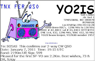
Yesterday evening, Szigy, callsign YO2IS, in Timisoara, Romania, 710 kms away, and I had a contact on the 2190m longwave band, which we will claim as the first ever Romania - Poland contact on that band, thereby adding Romania to my two prior "firsts" with the Czech Republic and Belarus.
I copy part of Szigy's email which he sent to me soon after our meeting 'on the air', particularly because it emphasises how challenging amateur radio communication is on longwave; as I know only too well myself, even over distances of just a few hundred kilometres. Szigy wrote:

"Dear Steve pleased to run a fine QSO with you, the very first SP-YO on 2.2Km. Signal was nice but with a deep QSB on the midle of the QSO. At the beginning had some problem with a flashover in the teflon feedtrough my window, it take one hour to change the isolator.Will send you a direct QSL in the next days. Once more thanks for the new one ! Have fun on VLF it's always a big chalenge, gl."

One of the challenges is typically the use of short inefficient antennas, ( because of the nearly 2.2km wavelength ), causing high voltages of several KV to appear at various places in the antenna system. Unluckily for Szigy during our contact, he had to take time out to tackle a problem of insulator flashover !
Earlier this week, I cleared ice and snow from my antenna in order to make it useable once more; but even then I had a flashover problem which I was able to prevent happening again, and fortunately nothing went wrong at my end during the contact with Szigy.

Stop press: In the last few minutes I have achieved another "first", Estonia. Incredible conditions on longwave this weekend, and some stations active making the most of them. What a start to 2011 on 2190 !

05 January 2011

Meteor scatter using the Quadrantids

The Quadrantids meteor shower, which appears to come from the direction of  the old star constellation of Quadrans Muralis near the Pole Star, has just intersected with the earth, as it does every year on the 4th January. I used the ionised trails produced as individual meteors burnt up in the earth's atmosphere to reflect my 50MHz radio transmissions to make contact with other radio amateurs in Denmark, Slovenia, England and the Netherlands by exchanging short, ( for obvious reasons ), text messages with them. The data transmission mode is called WSJT/JT6M, and I used the 500 watt amplifier featured on 25th January and 12th May 2010.
The screen shot shows one of Dick's, ( callsign G1CWP ), signals which I received during my contact with him in West Sussex, in the UK at a distance of 1451kms from me. The burst of signal has the characteristic profile of having been reflected by a meteor trail with its steeply rising leading edge as the trail quickly forms and peaks in intensity, followed by a more gradually falling trailing edge as the intensity subsides until the event is over.
I try to participate in all the major meteor showers during the course of a year; Quadrantids ( January), Lyrids ( April ), Perseids ( August ), Orionids ( October ), Leonids ( November ) and Geminids ( December ).